| 1. |
The procedure for the swing test
is based on the `Lamboley Test' used by the International Finn
Class.
The hull is suspended from brackets hanging from a transverse
beam which forms the swing axis.
The brackets locate on the hull below the rubbing strake. The
bracket design allows the hull to be supported at 2 different
heights relative to the swing axis. The swing period is measured
at each height. |
| 2. |
The swing period may be measured
using either:
| (i) |
A stop watch with 1/100 second readout. |
| (ii) |
An electro-optical device, such
as a photo-electric cell linked to an electronic timer or micro-computer.
These notes assume the manual, stopwatch method is used. |
|
| 3. |
If the weight of the hull is not
known, weigh the hull in conditions as defined in rule 3.2.7.
Record as 'M' kg. |
| 4. |
Suspend the hull, supported on the
brackets in position S1 as shown in the diagram, so that it is
level fore and aft in condition as for weighing. When level the
height of the sheerline at the stem will be 380mm more than the
height of the Aft Measurement Point (AMPt) above a level floor.
Assuming a level floor the error in fore and aft level will be
not more than 15mm in 3350mm, ie less than 0.5%. If the true
sheer height at the stem is known, from either the measurement
form or when the swing test is conducted as part of hull measurement,
apply a correction to the 380mm height as follows:
Subtract 540 from the sheer height. Add result to 380.
e.g. sheer height = 530: 530 - 540 = - 10: 380 + (-10) = 370
sheer height = 555: 555 - 540 = + 15: 380 + (+15) = 395
Ensure that the suspension axis is at right angles to the fore
and aft line of the hull. When it is, the distance from the aft
end of each bracket to the transom will be the same. Mark the
bracket position on the hull. |
| 5. |
Measure:
| (i) |
the horizontal distance from the
vertical plane through the pivot point of the transverse beam
and the transom. Record as 'CGH'. |
| (ii) |
the height of the support axis above
the underside of the hull. Record as `d'. |
|
| 6. |
Set up a support post for a reference
pointer close to the bow. Ensure it is just clear of the hull
when the hull is swung. |
| 7. |
Mark a level datum on the reference
post aligned to a clearly defined mark or feature on the hull,
eg the underside of the rubbing strake. Mark a swing start point
on the post 50mm below the level datum. |
| 8. |
Depress the bow to the start position
and release. Allow at least 1 complete cycle for the system to
settle. |
| 9. |
Start the stopwatch as the bow passes
the level reference. Count and time not less than 10 complete
cycles. Record as 'TTI'. |
| 10. |
Calculate the mean period for the
number of cycles completed, eg record mean period as 'TI'. |
| 11. |
Repeat steps 6 to 9 with the hull
suspended on the brackets in position S2. It is important that
the brackets are set at the same fore and aft position on the
hull as for S1, using the marks made in the procedure of paragraph
4. Record mean period as 'T2'. |
| 12. |
Calculations:
| (i) |
Calculate the height of the swing
axis (a) above the centre of gravity [CG] and radius of gyration
[RG] by either:
| (a) |
solving the following equations:
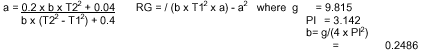
(constant)
or |
| (b) |
entering T1 and T2 in the tables
in the Europe Measurement Manual.·Calculator and computer
programs for calculating 'a' and 'RG' from 'T1' and 'T2' are
given in the IYRU Measurement Manual. |
|
| (ii) |
Calculate the Mass Moment of Inertia
(I)as follows:
I = M x RG2 where: M is the mass of the hull |
| (iii) |
Calculate the height of CG above
the underside of the hull (CGV) as follows:
CGV = (d - a) x 1000mm |
|
| 13. |
Record data on the measurement form. |